

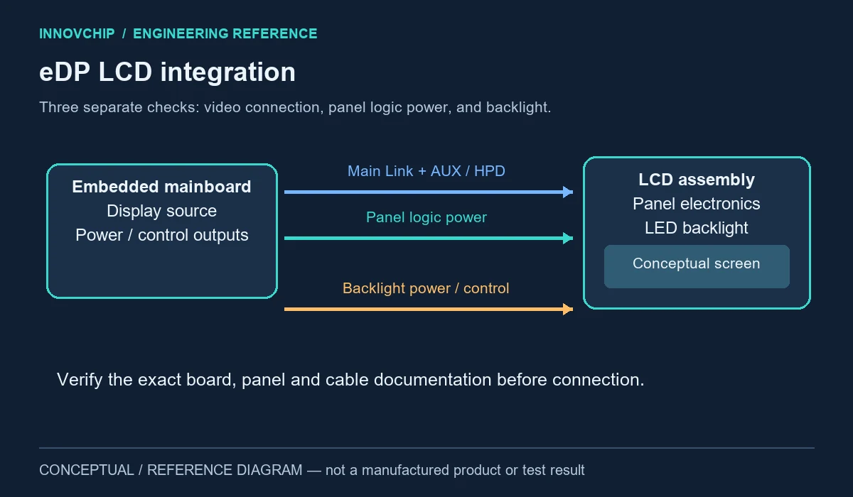
Engineering reference only: This article describes a proposed integration method, not a verified InnovChip customer delivery or completed physical prototype. No project-specific measurements or test results are claimed.
Direct answer: eDP integration requires a compatible video link, verified connector pin mapping, correct panel logic power, a suitable backlight supply and control interface, and the exact panel-specific sequencing. An illuminated backlight alone does not confirm video-link operation.
Definition: Embedded DisplayPort (eDP) is a digital interface used to connect an embedded display source to an internal display panel.
Engineering Reference Design: LCD Interface, Power Sequencing, Backlight Control and Hardware Validation
Project Overview
Integrating an LCD panel with an embedded mainboard is a common engineering requirement in industrial control equipment, embedded computers, machine interfaces, medical equipment, test instruments and customized electronic products.
A compatible embedded mainboard with an eDP interface can connect to an LCD panel through an appropriate cable assembly. Depending on the hardware architecture, separate connections may also be required for panel power and LED backlight control.
Although the physical connections can be simple, successful integration depends on several electrical, firmware and mechanical compatibility requirements.
This engineering reference case explains the design process for integrating an eDP LCD panel with an embedded mainboard and establishing a repeatable hardware validation procedure.
Project classification: Engineering reference design
Interface technology: Embedded DisplayPort (eDP)
Application: Embedded and industrial LCD systems
Development disciplines: Hardware integration, power architecture, display configuration and system validation
Physical prototype status: Not claimed; no project-specific test results are provided
1. Engineering Objectives
The system should be designed to:
- Establish a compatible eDP video connection between the mainboard and LCD panel.
- Provide the correct LCD panel logic power.
- Support the specified LED backlight power and control interface.
- Respect the required power-on and power-off sequence.
- Configure a display mode supported by both the mainboard and panel.
- Verify stable image output and backlight operation.
- Identify electrical, mechanical and firmware integration risks before prototype release.
Successful integration requires more than obtaining an illuminated screen. The system must also operate consistently during startup, shutdown, display mode changes and normal working conditions.
2. Proposed System Architecture
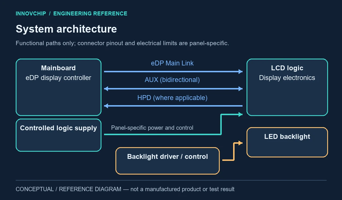
The proposed system contains five functional subsystems.
A. Embedded Mainboard
The embedded processor or display controller generates eDP video output and manages the display initialization process.
B. eDP Signal Interface
The interface includes high-speed display data lanes, an AUX communication channel and applicable Hot Plug Detect (HPD) signaling.
C. Panel Logic Power
A controlled power supply delivers the correct operating voltage to the LCD panel logic electronics.
D. LED Backlight Subsystem
The LED backlight receives appropriate power through a compatible driver or integrated backlight power circuit. Brightness control may be implemented through PWM or another supported control method.
E. LCD Display Assembly
The display assembly receives video data and provides the image output. Mechanical mounting, cable orientation, connector retention and grounding are also integration considerations.
Functional Signal Path
Embedded Mainboard
→ eDP Main Link / AUX / HPD
→ LCD Display Electronics
Panel Power Supply
→ Controlled Panel Logic Power
→ LCD Display Electronics
Backlight Power and Control
→ Compatible LED Backlight Driver
→ LCD Backlight
The exact topology depends on the selected mainboard, LCD panel and backlight architecture.
3. Interface Compatibility Requirements
Before connecting the hardware, engineers must confirm that the two devices are electrically and logically compatible.
3.1 LCD Panel Parameters
The LCD panel datasheet should identify:
- Manufacturer and exact panel part number.
- Native display resolution and supported timings.
- eDP lane count and link-rate requirements.
- Panel logic supply voltage and current limits.
- Connector type, contact orientation and pin assignment.
- AUX and HPD interface requirements.
- Backlight supply or LED driver requirements.
- Backlight enable and brightness control characteristics.
- Required power-up and power-down timing.
- Mechanical dimensions and mounting requirements.
3.2 Mainboard Parameters
The mainboard technical documentation should identify:
- Processor or graphics-controller display capability.
- eDP interface version and supported operating modes.
- Supported link lanes and link rates.
- eDP connector pin assignment.
- Panel logic power output capability.
- Available backlight power and control outputs.
- BIOS, firmware or operating-system display settings.
- Display initialization and power sequencing behavior.
3.3 Cable and Connector Verification
An eDP-compatible connector does not guarantee matching pin assignments.
Different boards and display panels can use different power, control and signal arrangements.
Before powering the system, the cable assembly must be verified against both electrical schematics or manufacturer-approved pinout documentation.
Do not connect a panel based only on the connector’s physical appearance or pin count.
4. Hardware Connection Procedure
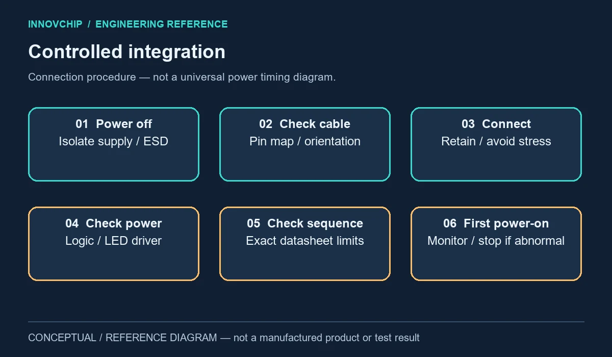
The following sequence describes a controlled integration procedure.
Step 1 — Power Off the System
Disconnect the mainboard from the power source.
Apply appropriate ESD protection and ensure the system cannot be energized during cable installation.
Do not assume that an eDP connector supports hot plugging.
Step 2 — Verify the Display Cable
Confirm that the selected cable matches both the LCD panel and mainboard connector pin assignments.
Verify connector orientation, cable retention, grounding and signal mapping.
Step 3 — Connect the LCD Panel
Install the approved eDP cable assembly into the LCD panel connector.
Secure the connector’s locking mechanism as specified by the manufacturer.
Avoid excessive cable bending or mechanical stress.
Step 4 — Connect the Mainboard Interface
Connect the cable to the mainboard’s designated eDP interface.
Confirm the mapping of video signals, panel logic power and control signals.
If separate connectors are provided for the backlight, verify their pin assignments and electrical ratings independently.
Step 5 — Verify the Backlight Subsystem
Confirm that the LED backlight driver and power source match the LCD assembly requirements.
Check the backlight enable signal, brightness control interface, voltage and current limits.
Never connect an unregulated supply directly to an LED backlight that requires a constant-current driver.
Step 6 — Confirm Power Sequencing
Verify the required panel power, eDP initialization and backlight enable sequence using the exact panel and board documentation.
The backlight must not be enabled outside the permitted sequence.
Step 7 — Perform Controlled First Power-On
Apply power using the specified supply arrangement and appropriate current protection.
Observe input current, supply stability, abnormal heating and display behavior.
If abnormal current, unexpected voltage or incorrect signal behavior is detected, immediately stop the test and investigate.
Step 8 — Configure and Verify the Display
Confirm that the mainboard detects and initializes the connected panel.
Verify the selected display timing, image output, brightness control and startup behavior.
Do not treat illumination alone as proof of successful eDP link operation.
5. Engineering Validation Plan
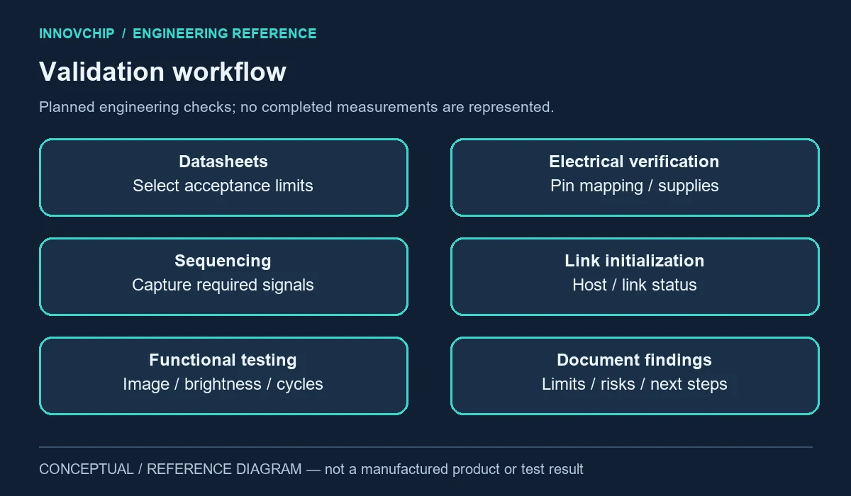
| Test | Validation Method | Acceptance Principle |
|---|---|---|
| Cable compatibility | Pin-to-pin mapping against documentation | All relevant connections verified |
| Panel logic supply | Measure supply at appropriate test points | Within panel datasheet limits |
| Power sequencing | Capture required signals with oscilloscope | Within specified timing requirements |
| eDP initialization | Review host/link status where available | Successful link initialization |
| Display output | Run image and test-pattern checks | Stable, correct image |
| Backlight operation | Test enable and brightness controls | Correct operation within ratings |
| Startup and shutdown | Repeat controlled power cycles | No unexpected or unsafe behavior |
| Thermal behavior | Measure relevant operating temperatures | Within component limits |
| Mechanical integration | Inspect connectors and cable routing | Secure assembly without interference |
Validation status: This table defines intended engineering checks. It does not represent completed physical tests.
Specific electrical limits and acceptance criteria must be derived from the selected component datasheets and system requirements.
6. Common Integration Problems
Problem A — The Screen Remains Black
Possible causes include incompatible panel power, incorrect pin assignment, failed eDP link initialization, unsupported display configuration or disabled backlight.
The first diagnostic step is to determine whether panel logic power, eDP signaling and backlight operation are functioning independently.
Problem B — Backlight Is On but No Image Appears
An illuminated backlight does not establish that video data has been received.
Engineers should inspect the eDP connection, supported display modes, link training status and display initialization configuration.
Problem C — The Image Is Unstable
Potential causes include high-speed signal integrity problems, cable issues, unsuitable display timings, power-supply instability or incorrect interface configuration.
Problem D — The Screen Works Only After Rebooting
This may indicate initialization, HPD handling, sequencing or firmware configuration problems.
Timing measurements and startup-state logging can help identify the cause.
Problem E — The Display or Board Heats Unexpectedly
Stop testing and investigate supply voltages, current consumption, backlight drive conditions and possible connector or wiring errors.
7. Engineering Deliverables
For a complete customer-specific development project, the expected deliverables may include:
- Mainboard-to-panel compatibility assessment.
- LCD interface pin-mapping documentation.
- Cable and connector definition.
- Panel power and backlight control design.
- Electrical schematic, when custom interface hardware is required.
- PCB layout and production files, when a custom PCB is commissioned.
- Firmware or BIOS configuration documentation, where applicable.
- Hardware bring-up and test procedures.
- Measured validation report after prototype testing.
- Final integration recommendations and identified limitations.
Deliverables and ownership of design files should be agreed within the project scope.
8. Potential Applications
This architecture is relevant to:
Industrial Human-Machine Interfaces: Equipment dashboards, machine status panels and factory control terminals.
Embedded Computer Systems: Integrated displays for industrial computers and compact computing platforms.
Testing and Measurement Instruments: Custom screens for laboratory devices, diagnostic instruments and electronic testing systems.
Customized LCD Products: Product-specific display integration requiring defined mechanical, electrical and firmware interfaces.
Display Retrofit Engineering: Assessment of whether an existing LCD module can be integrated with a replacement controller or mainboard.
9. Project Development Workflow
A customer-specific development engagement would normally follow this workflow:
Requirements Review → Component Compatibility → Electrical Design → Cable and Power Verification → Prototype Integration → Bring-Up → Validation → Engineering Documentation
The actual scope depends on the level of customization needed.
A direct integration project using existing compatible components may require substantially less engineering work than a new controller PCB development project.
10. Frequently Asked Questions
Can any LCD panel connect to an eDP mainboard?
No. Interface type, signal configuration, power requirements, connector pinout, display timing and backlight compatibility must be verified.
Is connecting the eDP cable enough to power the screen?
Not necessarily. The panel requires compatible logic power, and the LED backlight may need separate power and control circuitry.
Does eDP provide both display data and backlight power?
eDP provides a display interface, but actual panel power and backlight power depend on the implementation. These must not be assumed to be supplied by the eDP data lanes.
Can an industrial mainboard support a custom LCD panel?
Potentially, provided the display controller capabilities, electrical interface, firmware configuration and power architecture meet the panel requirements.
Is custom PCB development always necessary?
No. When existing hardware is fully compatible, integration may require only an approved cable assembly and configuration. Custom circuitry may be required when electrical interfaces or control requirements differ.
How can display reliability be verified?
By checking the electrical interfaces, power sequencing, link initialization, repeated startup behavior, image quality, backlight controls, environmental requirements and mechanical assembly.
11. Engineering References
- Intel — Embedded DisplayPort Backlight Control Signals: https://edc.intel.com/content/www/us/en/design/products/platforms/processor-and-core-i3-n-series-datasheet-volume-1-of-2/001/embedded-displayport-edp-backlight-control-signals/
- Texas Instruments — TIDA-01008 Optical Sense Backlight Reference Design with Temperature Sensing: https://www.ti.com/tool/TIDA-01008
- Texas Instruments — TIDA-01584 Power Sequencing Reference Design: https://www.ti.com/tool/TIDA-01584
These references illustrate relevant design principles. TIDA-01584 is a general load-switch power-sequencing example, not an eDP panel timing specification. Final implementation must use the applicable mainboard and panel datasheets.
12. Custom LCD and Embedded Hardware Development
InnovChip provides a contact point for discussing custom electronics engineering requirements, including embedded board integration, interface design, PCB development and hardware verification.
For an initial technical review, customers can provide:
- Mainboard model and technical documentation.
- LCD panel part number and datasheet.
- Intended application.
- Power-supply specifications.
- Display resolution and mechanical constraints.
- Prototype quantity and development requirements.
Discuss Your Project
Website: https://innovchip.net/
Contact InnovChip to discuss the documentation and scope. Related services: PCB design and embedded Linux development.